CadSoft Eagle Professional 6.3.0

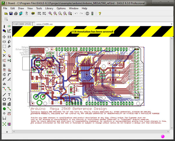
Cadsoft Eagle - это комплексное средство для разработки печатных плат, начиная с создания принципиальной электрической схемы и заканчивая созданием печатной платы и её трассировкой. Кроме этого программа имеет довольно большую библиотеку, содержащую множество стандартных и достаточно распространённых электронных компонентов.

Одним из основных достоинств данного пакета профессионалы выделяют полную синхронность изменений в проекте. К примеру, если вы изменили или удалили какой-либо компонент на схеме, это тут же отразится на рисунке платы. В таких программах, как ACCEL EDA, P-CAD и OrCAD необходимо постоянно контролировать весь проект, при малейших изменениях и на любом этапе работы. Кроме того, в EAGLE откат событий (UNDO) возможен на любое количество действий (такое не позволяет делать даже самый мощный на сегодняшний день CAD – ACCEL EDA).
Программа включает в себя:
- Schematic Module - модуль для создания принципиальных схем. Имеет удобный интерфейс, сетку для выравнивания компонентов и электрических линий, элементы для рисования на листе.
- Layout Editor - редактор печатных плат. Позволяет размещать компоненты на будущей ПП, имеется проверка на наличие ошибок, вспомогательные линии для упрощения процесса ручной трассировки, средства для нанесения шелкографической маркировки на ПП.
- Autorouter - модуль для автоматической трассировки печатных плат. Большое количество настроек позволяет повысить качество автотрассировки.
- Library Editor - весьма гибкий и удобный редактор библиотек.
В стандартный комплект поставки входят также модули, проверяющие правильность подключения электрических цепей (ERC – Electrical Rule Check) и правильность расположения компонентов на плате (DRC – Design Rule Check). Причём две последних операции выглядят намного приятнее, чем в более продвинутых системах. Программа проверяет правильность дизайна и соединений так, что пользователь вообще не знает, что этим занимается какая-то посторонняя утилита. Следует отметить, что пользователю не приходится запускать для этого различные программные модули, как это сделано в P-CAD или ACCEL EDA - все переходы осуществляются внутри самой программы. Имеется также возможность заливки заданного пространства полигонами.
EAGLE позволяет проектировать многослойные платы, содержащие до 16 слоёв и имеющие размеры 1626х1626 мм при разрешающей способности 0,0001 мм. Систему единиц (дюймовую или метрическую) можно изменить на любой фазе работы с проектом без каких-либо потерь.

ОС: Windows XP, Windows Vista, Windows 7
Platforms:
- Linux: libpng and libjpeg directly linked into the executable to get rid of dependency and availability of according system libs.
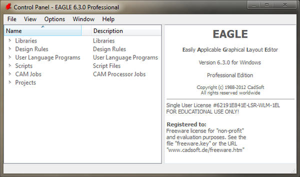
Control Panel / Preview:
- Preview extensions for board and schematic. Sheet descriptions and size information are also displayed.
- Beside file path indication of date and size of the currently selected file in the status bar.
- Preview for packages: Display a ruler to indicate the size.
User Language:
- Added new User Language object members UL_DEVICE.activetechnology, UL_DEVICESET.activedevice and UL_INSTANCE.part.
- Extended the User Language data type 'string' to support unicode characters.
- Modified handling of the default assembly variant in ULPs:
the function variant() returns "''" for this and the function setvariant() can be called with "''" or "". - Now the objects of "Arbitrary Pad Shapes" are available in ULPs through the loop members UL_CONTACT.polygons() and UL_CONTACT.wires().
CHANGE command:
- Added missing option DTYPE for dimension types.
DIMENSION command:
- Selection of rectangles and origins of elements or parts.
- Snap to objects on defining the second dimension point.
TEXT command:
- Now text objects can contain more than one line. Line distance can be set.
Note: Older V6 versions can read these texts but not display them correctly.
Miscellaneous:
- Now the editor for descriptions can edit different languages if existing.
- English and the current local language are always available.
- Now duplicate layer names are tolerated for compatilibility reasons (even though they should not be used).
- DesignLink: Search text field now with history, filtering of results.
- To avoid confusion, editing the coordinates of rotated rectangles in the Properties dialog is no longer allowed.
- PCB quote service:
- Quote parameters now go to Element14, where regional specific partners are offered.
- Parameters for assembly service were added.
- Added a warning if changing the assembly variant in the CAM Processor.
- Now boards are stored with proper data of the current assembly variant.
- Reduced line width (0.4mm) if drawing the marking 'X' of not populated parts.
- Add width and height in the Properties dialog for rectangles.
- Improved attribute dialog of devices to allow adding new attributes with empty values via the command line.
Bugfixes:
- Fixed unnecessary warnings about coarse grid values if pasting directly into the board.
- Avoid inconsistency in case Sch.Cmd.Add.AlwaysUseDeviceNameAsValue set to 1 if the part value is cleared later.
- Fixed PINSWAP: ensure proper relocation of already routed wires on pads.
- Fixed an inconsistency: do not allow PINSWAP or GATESWAP if an affected pin is connected to several pads.
- Formal correction of eagle.dtd (comments not allowed inside 'ATTLIST').
- Attributes with reserved names (like 'NAME', 'VALUE' etc.):
- Prevention of creation of such attributes except 'VALUE' in library editor.
Parts/elements from devices with this attribute take over the attribute value as part/element value. The attribute itself is no longer accessible. - The VALUE attribute is also used in case of CHANGE package/technology or REPLACE by a device with such an attribute.
- Prevention of changing of smashed reserved placeholder texts by ATTRIBUTE command:
In this case the attribute list of the part or element is displayed instead. - Improved drawing precision for arcs.
- Prevention of creation of polygons with only two points and overlapping wires.
- Fixed connectivity of net/bus wires or junctions if added to a group with ctrlclick and moving this group.
- Fixed moving a group containing a polygon from one schematic sheet to another.
- Avoid inconsistency if copying parts with assembly variants.
- The alignment point of a dimension object is now automatically adjusted after changes by the Properties dialog.
- Correction of online help (function xmlelement()).
- Fixed unintentional changes of mirrored state after placing a text on specific layers (like Nets).
- Added UNDO/REDO of PREFIX changes (incl. marking file changed in library editor).
- Creation/deletion of attributes: Ensure proper redisplay of elements and instances, also after UNDO/REDO.
- Now the name of the design rules is stored in the board file again.
- Fixed polygon representation in signal layers after MITER or SPLIT.
- Prevention of moving a text of a smashed instance to another sheet without the instance itself.
- Fixed check box 'overwrites device name' in the Properties dialog of elements.
- Added missing info for 'Inner/Outer Layer Diam.' in the Properties dialog of vias.
- Now the polygon parameters Thermals and Orphans are only available if applicable (in the board editor).
- Fix for highlighting pins/pads at wrong location in PINSWAP command.
- Fixed drawing artefacts when dropping a polygon during construction.
- Fixed writing the XML data file for airwires in special case.
- Added missing default assembly variant ('') if looping through UL_SCHEMATIC.variantdefs or UL_BOARD.variantdefs.
- Prevention of changing the position or rotation in the Properties dialog of an element with the 'Locked' flag checked.
- Avoid a possible inconsistency if a net is automatically generated by moving an instance so that pins contact each other.
- Now undefined characters of the vector font are displayed as '?'.
- Omit printing of origins also for gates and elements (like for instances etc.).
- Added an error message if a CHANGE parameter is used in improper context.
- Now the update report XML file is opened in the external editor if necessary and one is defined by the user.
- Now the update report window is opened in readonly mode.
- Fixed OPTIMIZE/UNDO if during optimization a wire has been converted to an airwire.
- Fixed unintended connections if pasting a net and the corresponding board contains a signal without a net counterpart.
- Fix for print problem on Windows if called from command line editor (landscape was ignored).
- Fixed drawing the unpopulated cross of instances if modified through the command line (VARIANT).
- Fix for PDF print problem on MAC to avoid large and not searchable files.
- Changed handling of names in the VALUE command syntax to case insensitive.
- Fix in the Autorouter/Followme router: the extension objects of not conntected pads with arbitrary pad shape were not taken into account.
- Fix for drawing artefacts after pasting a dimension object.
- Fixed writing the XML data file for airwires with an invalid extent.
- Fixed selecting assembly variants in the combo box with single quotes in their names.
- Avoid unsuitable entries in Control Panel trees (e.g. 'User Language Programs' tree only for files ending with '.ulp').
- Fixed a crash if drawing dimension objects and the 'Dimension line width' is set to zero. In that case arrows are no longer filled.
- Fixed a crash if starting the Autorouter/Followme router with an active, but not available layer.
- Fixed ADD through the command line with assignment of an object name : the currently handled object has been dropped inadvertently.
- Fixed the attributes dialog of instances: a previous fix in version 6.2.1 has added by mistake the global attributes here.
- Fixed a crash when switching to a project using a recently deleted library.
- Fixed a possible loss of consistency after renaming a net with the NAME command or by placing a supply symbol if the target net exists already on a different sheet.
- Control Panel: Made Key F2 for renaming files work again.
- Removed useless Align combobox from parameter toolbar when running the LABEL command.
- Proper handling for changed device attributes in schematic when reset to device value from library.
- Fix for finding symbols with umlauts when adding them in device editor.
- Fix for possible crash when copying parts with assembly variants from one schematic to other.
- User defined context menus: Avoid definition of multiple identical menu entries for one object type.
- Avoid plain text descriptions in control panel turn into links after previous click on a link.
- Now global attributes are ignored as in version 5 if attributes of parts are accessed by ULPs.
- Fix for visibility of click state of buttons on MAC.
- Fixed mirroring of texts of dimension objects in mirrored layers like bDocu.
- Fixed handling of '+' characters in the ULP functions cfgget()/cfgset(); this character is valid e.g. in key assignments with modifiers.
- Fixed recalculation of the symbol bounds when editing a device set.
- Fix for disappeared preview in print dialog after printing on MAC.
- Fixed for displaying the pointer rectangle in the SHOW command in case it's a net containing only pin references (no wires).
- Fix for ensuring correct printer selection on Windows.
- Fixed inadvertently resetting of parameters (e.g. wire width) to factory defaults if loading another drawing.
- Fixed using the proper net class while subtracting pads with "Arbitrary Pad Shapes" from polygons (e.g. in RATSNEST).
- Fixed a possible "Abort: Unknown objectType..." during "Paste from file" if the pasted drawing contains wires of zero length.
- Fixed changing a variant via the command line on parts with overwritten values.
- Fixed changing value or technology of parts or elements with variants not having own value and technology (the variants kept the previous value and technology from default variant).
Скачать программу CadSoft Eagle Professional 6.3.0 (52,25 МБ):


Ээээх, хотя бы лет этак 20 назад, да эти программы.